 |
|
 |
Hole Depth Gauge
For use with nut plates
Instruction For Using The G11 Hole Depth Gage 1. Obtain the correct diameter gage for the hole being measured. |
G11-08 |
(5/32”) |
Gold |
G11-3 |
(3/16”) |
Red |
G11-4 |
(1/4”) |
Blue |
G11-5 |
(5/16”) |
Green |
G11-6 |
(3/8”) |
Violet |
|
|
|
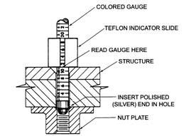
2. Insert polished (silver) end of gage into hole until bottoms on the nutplate.
3. Push Teflon Indicator Slide down to the structure.
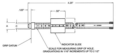
4. Read the number that is even with the structure.
5. This number will indicate the correct bolt grip length in 1/16” increments.
6. Example: the diagram indicates a -11 (11/16) grip length. NOTE: If indicator stops between lines, use the lower number. |
|
|
(*) General Notes: |
1-A pocket pouch with usage instructions, containing -08, -3 & -4 size gages, may be obtained by ordering part Number G11-20. |
Material: |
Gage: Aluminum alloy per QQ-A-225/T6. |
Indicator Slide: Teflon Bar stock per MIL-P-19468. |
Heat Treat: |
None. |
Code: |
Dash number indicates the nominal diameter in 1/16” increments of the hole to be measured. Exception: -08 size indicates 5/32” nominal diameter hole. |
G11-3 |
Example: |
(G11) Basic gage part number. |
(-3) 3/16” hole to be measured (red gage). |
|
|
|
|
Dash Number |
A |
B |
C |
Color |
(*) 8 |
0.163 |
0.375 |
0.12 |
Gold |
0.153 |
(*) 3 |
0.189 |
0.4 |
0.145 |
Red |
0.184 |
(*) 4 |
0.249 |
0.525 |
0.2 |
Blue |
0.244 |
5 |
0.31 |
0.562 |
0.255 |
Green |
0.305 |
6 |
0.373 |
0.625 |
0.318 |
Violet |
0.368 |
|
|
|